Dry Stacking of Tailings (Filtered Tailings)
Dry Stacking of Tailings (Filtered Tailings)
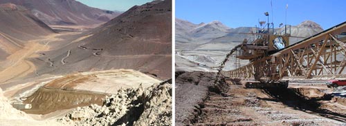
Figure 1: The La Coipa dry stack facility in Chile (Courtesy Anglo American/Debswana)
Introduction
Dewatering tailings to higher degrees than paste produces a filtered wet (saturated) and dry (unsaturated) cake that can no longer be transported by pipeline due to its low moisture content. These filtered tailings are normally transported by conveyor or truck, deposited, spread and compacted to form an unsaturated tailings deposit (Davies and Rice 2001). This type of tailings storage produces a stable deposit usually requiring no retention bunding and is referred to as ‘dry stack’. Figures 1 and 2 show the La Coipa dry stack tailings facility in Chile.
A typical moisture content of less than 20% is achieved by using a combination of belt, drum, horizontal and vertical stacked pressure plates and vacuum filtration systems (Martin, Davies et al. 2002). The term ‘dry cake’ or ‘dry stack’ is not entirely correct as the tailings have a moisture content several percent below saturation. However, this terminology has been adopted by regulators and designers (Davies and Rice 2001).
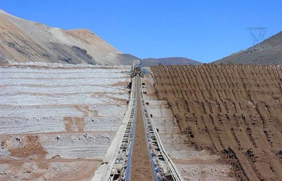
Figure 2: Dry stacking of tailings from a conveyor at La Coipa, Chile (Courtesy Anglo American/Debswana)
Advantages and Disadvantages
Like with thickened and paste tailings, the mechanical dewatering process compared to conventional slurry deposition increases costs. Producing wet and dry cake further increases this cost particularly if high throughputs are required. However, some of the many advantages to using dry stacking of tailings are:
Dry stack facilities are also easier to close and rehabilitate, require a smaller footprint compared to other surface tailings storage options (i.e. higher density), can be utilised in aggressive environments (e.g. undulating and steep terrain) and generate better regulator and public perceptions of tailings storage (Davies and Rice 2001).
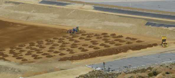
Figure 3: Dry stacking of tailings using truck transportation (© Jon Engels)
Some of the disadvantages to dry stack tailings are as follows:
However, it should be noted that the economics associated with implementing tailings filtration systems have decreased rapidly over the last 5 years. This is mainly due to the increase in capacity of modern filtration systems (e.g. increased filtration area of horizontal filtration belts) and operational optimisation such as minimised blinding of filter cloths.
Bauxite Residue (red mud)
The alumina industry produces bauxite residue (red mud) as a by-product of the refining process. Red mud storage facilities are often referred to as dry stack facilities, even though the tailings are commonly discharged into the facility by pipeline deposition. In reality this is conventional tailings storage (high rate thickened or paste), but the term 'dry stacking' refers to the final product based on the methods used to promote sedimentation and release of water within the facility and thus drying and strength gain. Due to the fine nature of the tailings properties, flocculation addition and mechanical disturbance are commonly used techniques, which increase overall operational costs.
Some low throughput alumina operations filter their tailings to produce a wet cake and thus 'dry stack' the tailings. This is the common definition of dry stack tailings or filtered tailings placement.