Cleveland Potash
Cleveland Potash - Boulby Mine, Cleveland, UK
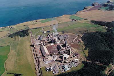
Figure 1: Cleveland Potash - Boulby Mine, Loftus, UK (Courtesy of CPL Ltd.)
Introduction
Cleveland Potash Limited (CPL) mines 3.0 mtpa of ore at the Boulby underground mine in north-eastern England, producing 1.0 mtpa saleable potash by conventional flotation processes. Two tailings streams are produced as a by product of potash processing:
Previously all process waste was re-pulped with sea water and discharged into the North Sea. Due to the presence of trace quantities of heavy metals (mercury and cadmium) in the insoluble clay, the permitted amount of insoluble waste that CPL can discharge into the sea has been substantially reduced.
CPL initiated a study in 1996 to investigate the feasibility of disposing filter cake as backfill in the worked out areas of the mine. The research addressed the following issues:
Following the positive outcome of this study, in 1998 CPL committed to a four year project involving extensive laboratory test work and the operation of a pilot-scale plant. The £3,000,000, 4-year project, which received financial support through the European Commission’s LIFE – Environment programme, was managed by CPL with the assistance of the UK’s Mineral Industry Research Organisation (Dodds-Smith 2003). The principal design consultants to the project were Paterson & Cooke Consulting Engineers.
The function of the backfill system is to re-pulp 200,000 tonnes of filter cake per year with sea water and hydraulically place it underground at as high a solids concentration as possible. The filter cake disposal is achieved through the following steps:
- Preparation
- Re-pulp the filter cake using sea water and transfer the filter cake backfill slurry to a storage tank close to No. 2 Shaft.
- Distribution
- Transfer the backfill slurry from the surface to panels underground for placement via a gravity reticulation system. The basic requirements for the Boulby backfill system are detailed in Table 1.
| Item | Value/Comment |
|---|---|
| Backfill material | Filter cake |
| Carrying fluid | Sea water |
| Backfill tonnage | 200,000 t/y |
| Backfill density | Maximum practicable (1,400 to 1,600 kg/m3) |
| Operational days | 330 day/year |
| Placement | 3 times per day |
| Placement distance | 5,500 to 11,040 m |
| Gravity head available | 908 m to 1,100 m |
Table 1: Backfill system requirements
Backfill slurry properties
The results of tests with binder addition indicated that binder addition rates of between 10% and 15% were required if the backfill was to gain sufficient strength to enable it to be used for underground support. Following careful consideration by mine staff, it was decided not to add binder to the backfill for the following reasons:
The system design is based on the slurry properties determined from the on-site pilot plant loop tests (Fehrsen et al 2002). The properties are detailed in Table 2. Figure 2 shows backfill discharge into a placement panel.
| Item | Value/Comment |
|---|---|
| Filter cake solids density | 2,525 kg/m3 (typical) |
| Sea water density | 1,026 kg/m3 |
| Slurry density | 1,495 to 1,585 kg/m3 |
| Slurry concentration by volume | 31.3% to 37.3% |
| Slurry rheology | Bingham Plastic Model Yield stress: ty = 50 C1.8/(0.47-Cv) Bingham viscosity: K = µw (1- Cv/0.36)-0.9 |
Table 2: Backfill slurry properties
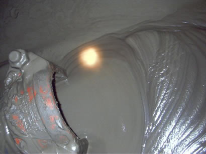
Figure 2: Backfill displacement (Paterson & Cooke Consulting Engineers (Pty) Ltd)
Underground placement
Placement panels
The principal considerations in selecting mine areas suitable for backfilling are:
Rock mechanics implications
Calculations undertaken by the CPL’s rock mechanics department show that on completion of mining, the pillars between adjacent panels undergo consolidation and lateral deformation. As a result the cross sectional area of the panel will reduce by 36% within 4 years of mining with a further 26% reduction in the original cross section area occurring over the next decade.
An allowance is provided to accommodate the volume of backfill that could be displaced by the reduction in the panel area due to overburden load.
Ventilation
Studies by the Mine Ventilation Department confirm that the backfilling of worked out panels would not adversely affect the ventilation system due to changes in the airflow pattern or give rise to a significant increase in humidity as a result of the evaporation of moisture from the surface of the backfill.
System commissioning
Preparation Plant
CPL commissioned the surface preparation plant. Before commissioning the underground distribution system, PCCE validated the operation of the surface plant with particular emphasis on the quality control loop. The surface preparation plant performs to specification and controls the backfill slurry viscosity as required. The main problems encountered during commissioning were:
Distribution system
The installation of the underground piping and shaft column was completed while PCCE was on site. PCCE assisted CPL with the pressure testing of the shaft column and underground piping.
Following the pressure test of the shaft column and underground piping, the performance of the energy dissipaters were validated. The two smaller energy dissipaters controlled the flow to approximately 71% of the design flow rate at the duty head. This is less than the design flow rate but it will increase as the units wear, although the charging of the shaft column and filling of the underground range does take longer than estimated as a result. The larger energy dissipater unit controlled the flow rate to 91% of the design flow rate at the duty head. The first backfill placement was on 16 May 2003. Two more pours were possible before the Treatment Plant shutdown on 23 May 2003. The main problems experienced during commissioning were:
The measured flow rates during initial placement were slightly higher than the design flow rates. This was due to the cautious approach adopted during commissioning:- the backfill was prepared to a viscosity lower than the design value for the initial trials. The viscosity is to be gradually increased with future pours until the design flow rate is achieved.
Pressure traces were recorded on start-up and shutdown using high speed data acquisition equipment to compare the actual transient pressures with the predicted transient pressures. The maximum transient pressure step measured was approximately 2 MPa compared with 4.4 MPa predicted. This is most likely due to differences in the flow model used in the transient analysis and the non-Newtonian flow behaviour of the slurry as well as slower valve operating times.
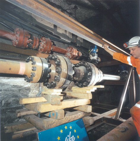
Figure 3: Energy Dissipators (Paterson & Cooke Consulting Engineers (Pty) Ltd)
Operating Experience
The new surface preparation plant has replaced the old kibbler and mixer tanks which repulped the filter cake for disposal to sea. The new plant has proved significantly more reliable.
The backfilling operation is initiated by the operator in the mine control room and shuts down automatically. The control also monitors pressure and flow to shut the system down in the event of a failure. The backfill system has proved simple to operate and the system flow rates have been consistent over the 6 months of operation indicating the reliability of the viscosity control.
Soon after backfilling operations began the insoluble clay content of the waste stream reduced due to changes in the ore mined. This means that less waste needs to be placed underground. Suitable void space underground is limited and so to prevent unnecessary use of the void space, currently backfill is only placed once every two weeks. The system has not blocked following start up of the system after a two week shutdown with a full column indicating that there is no significant settlement of material in the pipe. For most of 2004 the clay insoluble content is expected to remain low and the system will be drained and shutdown for six to eight months.
A system of regular inspection of the shaft and horizontal delivery pipe has been implemented to monitor the pipeline wear rate.
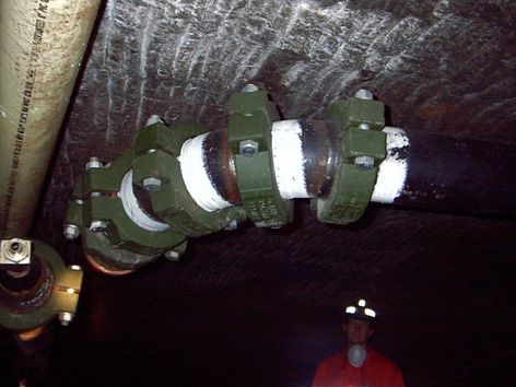
Figure 4: Backfill 90 degree bend (Paterson & Cooke Consulting Engineers (Pty) Ltd)
Conclusions
The successful commissioning of the backfill system in May 2003 has provided the potash industry with a proven alternative method of tailings disposal to the conventional options of disposal at sea (as currently used by Boulby) or placement in a conventional surface tailings depository. The system has a number of unique features:
Reference
Wilkins, M; Fehrsen, M; Cooke, R, (2004). Boulby Mine Backfill System