Surface Tailings Containment
Surface Tailings Containment
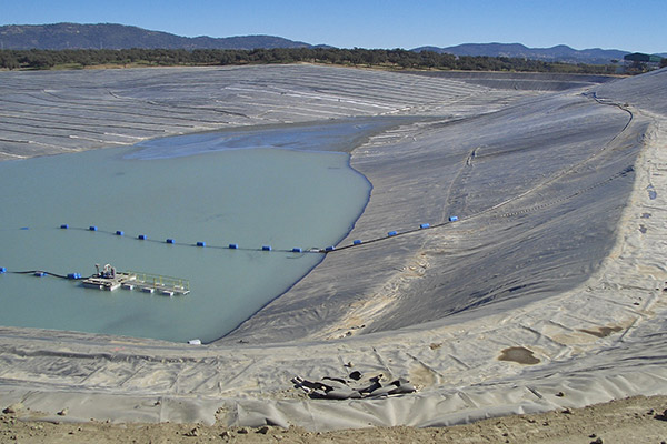
Geomembrane lined valley style tailings storage facility
© Jon Engels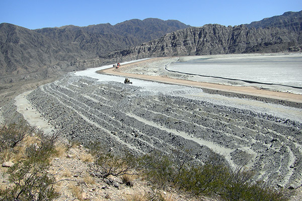
Modified centreline valley style tailings storage facility
© Jon Engels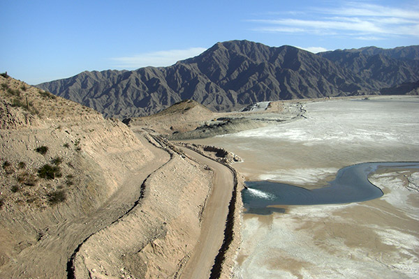
Side valley tailings discharge
© Jon EngelsTailings stored on the surface are usually deposited within purpose built retaining embankments. Conventional impoundment storage is the most common and normally has higher embankments than thickened, paste and dry stack storage facilities. Embankments for conventional storage facilities are designed to retain tailings and water (Vick 1990) whereas thickened, paste and dry stack facilities have embankments designed to retain runoff, bleed water and fines rather than the weight of the tailings mass itself. The design principles of surface thickened, paste and dry stack are to create a self supporting mound of tailings (ICOLD and UNEP 2001) rather than relying on the retaining forces of embankments to prevent mobilisation.
In-pit, co-disposal and offshore are alternative tailings discharge methods that are not widely practiced but can be useful under certain circumstances. In-pit storage involves filling mined out open pits with tailings. Generally no liner systems are used and the tailings are stored above groundwater level (Ritcey 1989). Co-disposal is a mixing of tailings and coarse mine waste to produce a single waste stream (Martin, Davies et al. 2002) or by co-placement seperating the two waste streams in a single storage facility. This method of tailings storage is most suitable to the backfilling of voids (underground and open pit), the covering of conventional tailings storage methods and the construction of elevated waste heaps (providing a water containment system is in place)(DME 1999).
Offshore tailings disposal is the discharge of tailings to natural bodies of water (Vick 1990). Submarine Tailings Disposal (STD) is perhaps the most common offshore disposal technique and involves the deep water discharge of tailings to the sea (Moore, Pelletier et al. 2002).
Various pages within this website present a brief overview of the various surface and offshore tailings storage methods used today. The following sections relate to conventional surface tailings storage.
Key site selection parameters
Site selection is the most important aspect in affecting the tailings storage facility design. Different sites have different characteristics and a suitable location is sort that is most practical in terms of cost and proximity to the mining and milling operations. The tailings characteristics will have an effect on the type of storage impoundment area, and therefore the site location (EC 2004).
Primarily the site selection is dependent on the storage capacity required of the facility, the site availability, the construction, operating and closure costs, geotechnical and geological conditions, the hydrology of the area, and the ease of the day to day operations. Other site selection considerations are:
Processing plant to storage site
Tailings are either pumped or gravity fed through pipelines or open flumes from the processing plant to their final storage location (ICOLD and UNEP 2001). The tailings flow is normally thickened at the plant to recover water for reuse in the mineral processing stage and to prevent unnecessary discharge and water management at the storage facility. For thickened and paste storage it is not uncommon to have the thickener(s) at or near the point of discharge to prevent high pumping costs and the need for positive displacement pumps (Fourie 2003). For dry stack facilities the final moisture content of the tailings prevents pumping and so truck or conveyors are used. For this type of disposal it is therefore more efficient to dewater the tailings at the plant (Davies and Rice 2001).
The distance to the tailings storage facility from the plant and the difference in elevation between these two locations can have a significant effect on the capital expenditure and the operating costs of tailings storage. The tailings and reclaim water pipelines can cost up to $500,000 per mile (Vick 1990) which puts a substantial cost burden on a more distant tailings storage site. Ideally the tailings impoundment should be located within four to five kilometres from the processing plant, but this will vary for special cases that require disposal of large volumes of tailings, or where site factors prevent the construction of a facility.
Tailings delivery and return water lines
© Jon Engels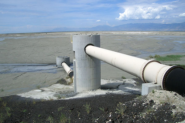
Tailings drop box at Kennecott Copper, UT, USA
© Jon Engels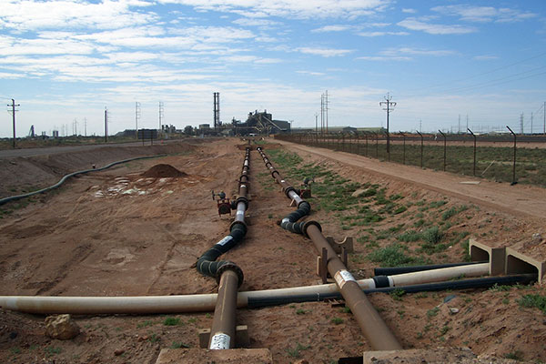
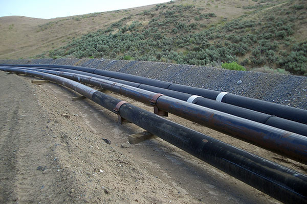
Tailings delivery lines with heat expansion sections
© Jon EngelsThe elevation of the tailings storage area in respect to the mill can influence cost of construction or operation. Ideally the proposed disposal site should be downhill from the plant to take advantage of the gravity flow of the tailings, thus reducing pumping cost (EPA 1994). If the gradient, and indeed the distance were large, then the cost of pumping the reclaim water would increase and drop boxes would be required to disperse the excess energy in the tailings pipeline (Vick 1990). The previous figure shows drop boxes being utilised to dissipate the energy of the tailings discharging into an impoundment. High flow rates increase the internal wear on the pipework and can therefore increase maintenance costs.
Facility layout
The layout of a surface tailings storage facility is dependent on both natural land forms as well as manmade engineered features (Ritcey 1989). The three main layout types for slurry impoundments are (Vick 1990; Norman 1998):
- Ring dykes (paddocks or cells)
- Valley impoundments – Cross valley, sidehill and valley bottom
- In-pit
To some degree, the design of the retaining embankment is independent of the type of impoundment layout. The only considerations are costs associated with starter dyke and subsequent raised construction, the volume of material required to establish a particular height, the tailings properties and the water storage requirements of the facility. Ideally topographical depressions are more advantageous for tailings storage as the volume of fill material required and the subsequent embankment heights are reduced.
Ring dyke
The ring dyke configuration (also known as a paddock or cell) is not dependent on topographical depressions as is the case with valley impoundments. This type of impoundment layout is therefore more flexible for site selection purposes and can usually be sited relatively close to the processing plant (Ritcey 1989). The embankments of a ring dyke impoundment require large volumes of fill material in relation to the storage volume produced. This is due to increased wall lengths as a consequence of complete containment of the tailings on all sides. The main advantage to this layout is that surface runoff cannot inundate the tailings storage area (EPA 1994) making the contained water within being entirely process or precipitation derived.
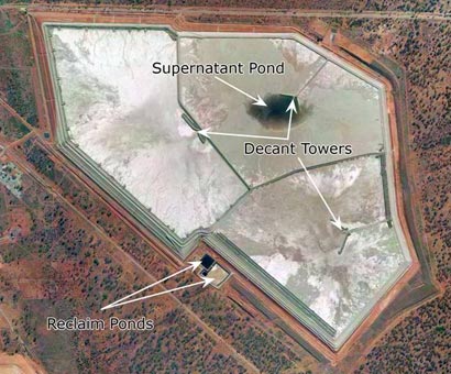
Ring dyke configuration (three cell arrangement) at Kalgoorlie Consolidated Gold Mines (KCGM), Western Australia (Courtesy Newmont Australia)
A raised ring dyke using the upstream method requires the least amount of embankment fill material but on each raise the storage volume decreases. This means the rates of rise of the embankments increase to generate the same storage volume after each lift. Excessive rates of rise leads to increased pore pressure and very low shear strengths (Jakubick, McKenna et al. 2003) which need to be limited to specific design requirements (SANS 1998). Such excessive loading has been the trigger for static liquefaction that has been the underlying cause for many tailings embankment failures (Davies, McRoberts et al. 2002).
Ring dyke tailings storage is common in Australia due to prodominant flat topography.
Valley impoundments
A valley impoundment is normally utilised to take advantage of natural topography (EC 2004). The three main types of valley impoundment are cross valley, sidehill and valley bottom. The cross valley design is similar to the layout of a conventional water storage reservoir in that an embankment is placed across the valley to dam a drainage area (Vick 1990). Ideally this type of impoundment should be sited at the head of the drainage basin to minimise surface water inundation. Diversion ditches, spillways or upstream water dams may be essential to divert/capture peak flood flows.
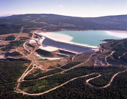
Cross valley tailings impoundment at Highland Valley Copper, BC, Canada (Courtesy of Teck)
The sidehill design relies on containment by embankments on three sides (Norman 1998). This type of valley design is similar to the ring dyke configuration but does not require complete containment due to the impoundment being situated on a slope. Upstream surface water accumulation can easily be prevented from inundating a sidehill impoundment as the entire valley is not dammed. Simple ditching and bunding can divert and control any required surface runoff water without the need for spillways or costly upstream water retention reservoirs. The sidehill design is best suited for slopes of less than 10% as the steeper the slope the more fill volume is required in the embankments in relation to the storage volume achievable (Vick 1990). If using the downstream and centreline embankment raising techniques the embankment fill volumes increase compared to upstream raises and can occupy potential storage space.
Sidehill tailings impoundments at a mineral sands mine in Western Australia (© Jon Engels)
Valley bottom impoundments are considered where the span of a valley is too large and high water runoff presents challenges for cross valley storage. Steep sided valleys may also make sidehill impoundments either impossible or unfavourable. Valley bottom impoundments are actually a compromise between a cross valley and a sidehill design and are normally built in multiple formation similar to sidehill facilities (EPA 1994). Diversion of existing stream channels may be required as valley bottom impoundments are usually sited in relatively narrow valleys (Vick 1990). This diversion channel will need to be designed to carry the full peak flood flow around the impoundment and prevent water encroachment on the embankment toes.
For Inpit storage see the relevant section here.