Water Management Considerations for Conventional Storage
Water Management Considerations for Conventional Storage
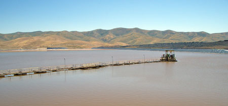
Figure 1: Water recovery from a conventional impoundment using a floating pontoon and walkway (© Jon Engels)
Introduction
Water has been the underlying source of virtually all failures of tailings storage facilities between 1980 and 1996 (Fourie 2003). All these failures have occurred at facilities that store their tailings by conventional impoundment methods. The liquefaction phenomenon, internal and external erosion, seepage and overtopping are some of the main water induced failure modes of tailings facilities (ICOLD and UNEP 2001). Increasing the pulp density of the tailings is the most obvious step to reduce water handling and subsequent storage requirements. Fourie (2003) also notes that the presence of large quantities of stored water is the primary factor contributing to most of the recent tailings storage failures. The risk of physical instability for a conventional tailings facility can be reduced by having good drainage and little (if any) ponded water. Simply put, ‘no water, no problem’.
Water management of a tailings facility not only involves the superficial water flows but the interception, collection and treatment of seepage. Control measures may be required to prevent levels exceeding regulatory licenses and tailings guideline documents (Ritcey 1989). This section reviews these key water management considerations for conventional tailings storage as well as the infrastructure required to control ponded water. The intention of this section is to highlight how problematic conventional storage can be to both design and manage.
This water management page is not relevant to High Density Thickened Tailings (HDTT), paste and dry stack facilities as little or no water is stored with the tailings. This strengthens the argument that these methods of surface tailings storage have a lower risk of failure as water management is reduced or virtually eliminated. However, reclaim ponds may be used to capture surface runoff or any bleed water as the tailings deposit within the facility.
Water balance and release
Establishing a stable water balance for a TMF during the design stage is one of the most important considerations to prevent water management problems occurring during operation and closure. Water plays a key role in the day to day responsibilities of a tailings operator and it is essential that a facility is designed to handle and control the required inflows and outflows as well as any unpredictable fluctuations (e.g. storms). Poor design of water management infrastructure and control methods can increase the risk of problematic situations occurring during the operating and closure stages (e.g. upstream inrushes, pipe bursts, low freeboard, seepage). During operation the plant will also demand a certain, and sometimes variable, flow of water that the surge capacity of the decant systems and reclaim/holding ponds have to cater for. Any water balance survey for a proposed tailings facility should take into account that higher volumes of water may require storage during the dry season to maintain plant production. Ice and snow melt, upstream inundation (valley impoundment) and severe storm reoccurrences (e.g. 1 in 100 year) should be considered when designing a TMF to prevent any loss of minimum freeboard levels.
When determining the water balance the various inputs and outputs of the proposed TMF will need to be considered. Wels et al. (2003) noted that determining the water balance of a tailings storage facility can be a difficult task if all the physical processes of water movements are to be considered. During the design stage a conceptual water balance of all inflows and outflows should be determined for a particular location and include all the worst case combination of risk factors (e.g. decant failure, storm, upstream snow/ice melt) (DPI 2003). A simple and accurate method to determine water balance of a TMF is to determine average annual water inflows and outflows as well as estimating seepage and evaporation rates. A more complex method is to use hydrogeological modelling methods (WMC 1998). Estimating the phreatic surface will help to determine seepage plumes and groundwater movement. Figure 2 shows the various water gains and losses for a typical conventional TMF. The seepage and evaporation losses will be predictions and should be included in any design proposal.
Figure 2: Water balance of a typical conventional tailings storage facility (Adapted from (Vick 1990))
Water stored in a tailings facility is either decanted to reclaim ponds or sent directly to the processing plant. If the plant requires none or only a small volume of the stored water then the remainder will need to be either sent to evaporation ponds or treated and discharged to the environment.
Supernatant pond
The control of the supernatant pond is probably one of the most important procedures in managing a TMF. Inadequate pond control can result in overtopping, increase in pore pressures, reduction of freeboard, high seepage rates and embankment settlement (Engels, Dixon-Hardy et al.). These few consequences can lead to instability and high risks of problematic situations occurring. For a conventional impoundment (particularly upstream and centreline designed) it is essential that the ponded water be kept to a minimum volume and the freeboard be sufficiently high all along the tailings embankment(s). Suitable monitoring and management of the supernatant pond is required to operate a TMF safely.
Decant systems
The decant system(s) of a TMF should be designed to cope with the day to day management of the supernatant pond as well as storm condition surges. The design of the decant should allow for a high surge capacity of storm water to compensate for near future storm events. If the pond cannot drain fast enough (decant system or reclaim/evaporation pond ingress restriction), then the freeboard of the TMF may be lost if a near future storm reoccurs. As a guide the decant system should be able to remove storm water in 2 – 4 weeks, but this is highly dependent on climate conditions (WMC 1998).
The two most common methods of water control within a tailings storage facility are a decant barge and a decant tower. A decant barge consists of a floating platform that houses the pumps used to reclaim water from the supernatant pond back to the processing plant or holding ponds. A decant tower is an intake structure consisting of a vertical or inclined hollow tower (riser) allowing the free water to be pumped out of the tower or drain by gravity via a buried conduit.
Decant tower
Decant towers can be very effective at removing ponded water from a tailings facility but can be very problematic. Decant tower systems come under increasing stress as more tailings are disposed of in an impoundment and consolidation occurs. Complete collapse of a tower system has occurred at some facilities as a result of this effect.
One major disadvantage to a decant tower is that the water has to be continuously positioned around the tower as unlike a decant barge a tower cannot be relocated. If a decant tower becomes inoperative (beached tailings moving the pond away from the tower) then emergency pumping or spillways will need to be implemented. Any tailings facility operating plan should have precise contingency plans documented in case a decant tower becomes inoperative either by isolation, blockage or failure.
There are two styles of decant tower as follows:
Seepage Decant Tower
A seepage decant tower is a standalone structure that is normally pumped dry without an underlying conduit. This style of tower is preferred compared to a cascade style tower as they don’t require raising, resulting in less day to day management and are more flexible in with regard to the position they can be constructed within a tailings storage facility.
The tower is normally constructed of concrete with slots installed at required spacing depending on the seepage flow rate into the tower. However, gabions can be used if the tower height is not too high. Slight movement or settlement of a closed bottom seepage decant tower will not affect the performance of the tower which is an advantage over a conduit style structure.
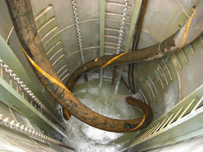
Figure 3: Inside a slotted decant tower (seepage tower) (© Jon Engels)
Cascade Decant Tower
Traditionally, a decant tower (cascade) is gravitationally drained by a connection to a horizontal conduit or pipe that can travel beneath the impoundment and through/under an embankment. However, this practice is antiquated and not used in modern designs due to the risk of the conduit collapsing allowing tailings or embankment fill to flow out of the impoundment (e.g. see Aitik failure below). The vertical riser of gravity decant towers is extended as the level of tailings in the impoundment rises. The decant tower skims off the clear water from the surface of the supernatant pond and carries it away by gravity through the underlying conduit (EC 2004).
The ever increasing weight of the tailings can crack and damage a decant conduit that flows underneath and through an impoundment facility (Engels and Dixon-Hardy 2004). Failures of decant conduits and towers can lead to water management problems that have caused impoundment failures in the past (ICOLD and UNEP 2001). It will not be immediately apparent to an operator that a decant system has failed until the decant outfall is showing signs of low flow or the presence of sediment (tailings). Water levels in the impoundment can rise rapidly and overtopping can occur if contingency plans are not implemented. The Stava disaster in Italy in 1985 was a good example of a decant conduit failure that created a rise in the phreatic surface of the embankment (Penman 2001). A rotational slip occurred causing tailings from the upper impoundment to inundate the lower impoundment which eventually overtopped and failed (Davies 2001). Tailings escaped down the hillside engulfing the town of Stava claiming the lives of 269 people. Stava remains as one of the world’s worst tailings disasters in terms of loss of human life.
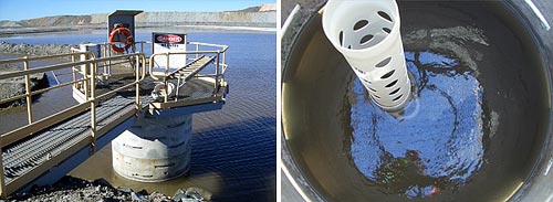
Figure 4: Decant tower with walkway (left), view inside the tower showing riser pipe and submerged decant collars (right) (© Jon Engels)
Cracking of a decant conduit can cause internal erosion which will eventually lead to impoundment instability. Ice thrusts can also generate movement in the riser that can crack the joints between the riser and horizontal conduit (ICOLD and UNEP 2001). Repairing the buried conduit is a near impossible task and far too expensive to carry out. The Aitik tailings dam failure in Sweden was triggered by a damaged concrete decant conduit. Cracks developed causing settled tailings to pipe through creating a sink hole (EC 2004). Figure 5 shows the extent of the breach and the cracks in the washed away conduit.
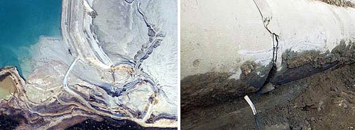
Figure 5: Aerial view of the embankment failure at Aitik (left) and the cracks in the decant conduit (right)
(Courtesy of Boliden)
Decant barge
Unlike decant towers that are gravity fed, a decant barge requires power to operate the pumps that decant the water from the supernatant pond. This increases operating costs as a constant and reliable power source is required to ensure the pumps operate. If a power failure occurs then no water can be decanted. It is good practice to have standby pumps and diesel generators to use in emergency or when a decant barge cannot cope with rapid ingress (e.g. storm conditions or when process water is required in vaster quantities). Before power or equipment failures occur there should be emergency procedures and response plans to rapidly mitigate any decant problems that can be implemented in both normal and storm conditions.
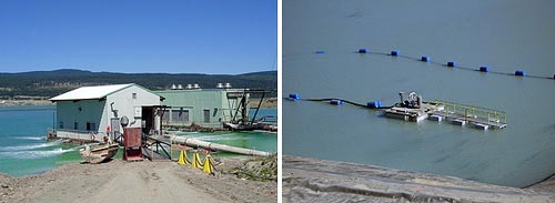
Figure 6: Fixed decant barge (left) and a mobile barge (right) (© Jon Engels)
The capacity of the barge(s) should be adequate enough to remove day to day decant demands as well as storm water accumulation. The barge should also be situated in an easily accessible location for maintenance and inspection purposes. Ideally this should be against the side of a valley wall (for a valley impoundment), or against the side of a jetty wall (either floatable walkway or purpose built) in an area of the impoundment where the ponded water is at it’s deepest. The water depth below the barge can influence the clarity of the decant water and prevents tailings being sucked up by the barge. As a rule of thumb, a minimum depth of two meters is preferred to prevent damage to the suction heads of the pump and to prevent tailings from being returned to the plant or holding ponds.
An important consideration, particularly for geomembraned lined facilities, is that a decant barge has to be properly anchored to prevent the barge contacting the sides of the facility that can tear the liner. High winds can break anchoring systems rendering a barge uncontrollable resulting in major damage both to the barge and liner system. Anchoring the barge to a small causeway is the preferred option to reduce the risk of contacting the embankment sides and to maintain an adequate depth of water below the barge should the level of water reduce.
A decant barge or submersible pump can be moved as the decant pond location changes and/or the tailings volume increases. For valley impoundments or in-pit disposal the decant barge or pump is generally retracted to keep the equipment close to the valley or pit walls. This makes it easier to access and prevents the use of heavy anchoring to control varied movement which can be expected the further away the equipment is from surface anchoring points. Each time a barge is moved to other cells the plant water demand should be calculated to ensure the barge is capable of meeting the demand from the water in the new cell.
Reclaim pond(s)
The reclaim pond(s) (or return pond(s)) store the water that is being decanted from the TMF. Reclaim ponds are sometimes referred to as decant ponds which in most parts of the world is another name for the supernatant pond. A reclaim pond is situated outside the confining walls of the tailings storage area a short distance away (figure 7). The water in the reclaim pond is either sent to treatment/polishing ponds for discharge to the environment or pumped back to the plant for use in the processing operation. Some reclaim water can be sent to evaporation ponds or sprays if the climate is suitable.
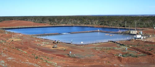
Figure 7: Reclaim ponds at Kalgoorlie, Western Australia (© Jon Engels)
The reclaim ponds should be suitably sized to balance the water inflows from the TMF’s supernatant pond with the normally variable outflows to the plant. For this reason the reclaim ponds can vary in volume and so an adequate depth is required to prevent overtopping and ensure the return pumps have sufficient suction head. The surge capacity should also be adequate to remove storm water flow rates from the TMF. This should be similar to the TMF’s (2 – 4 weeks depending on climate conditions) to allow for reoccurring storms (WMC 1998). This should be checked against the plant volume requirement and overspill/evaporation pond volumes.
The degree of design specification will be determined by the quality and quantity of the return water. The ponds will need to be suitably lined to prevent groundwater contamination (e.g. clay or normally HDPE/LLDPE lined). Prior to installation, the liner system should be checked to determine if the decant liquor will cause any chemical degradation. This is particularly true for HDPE where even UV radiation can degrade the liner (SANS 1998).
Reclaim ponds are particularly useful for tailings facilities that utilise the subaerial deposition technique as the supernatant pond can be drained or pumped into reclaim ponds increasing the beach exposure. This aids the drying and consolidating rates of the tailings in the TMF (DPI 2003).
Freeboard
Normally the minimum freeboard is determined by national/local legislation and/or company policies. It is essential in the design stage that water balance calculations take into account average and extreme conditions to prevent loss of freeboard during operation.
Freeboard is used to establish the elevation of the lowest point of the embankment crest relative to the normal or maximum operating levels of the supernatant pond (SANS 1998). Freeboard management is a critical factor used to control water of a conventional tailings storage impoundment (DME 1998). To promote good drainage of the embankments, the supernatant pond has to be as far away from the embankments as possible (maintain a high freeboard and wide beach). Ideally the pond should be of a small area, to reduce seepage, and be at a maximum depth at the decant facility to improve reclaim water clarity.
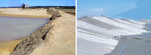
Figure 8: Loss of freeboard (left) and high freeboard (right). (© Jon Engels, Right picture courtesy of Anglo American)
The definition of freeboard varies in tailings guidance and legislation documents around the world. Confusion can arise where the freeboard is interpreted as the vertical height between the pond and the top of the beach OR the top of the embankment crest. This is further confused where the embankment crest is measured as the external rather than the internal height. The correct definitions of freeboard are (DME 1999):
Total Freeboard (freeboard): The vertical height between the waterline and the top of the embankment crest (internal). Total Freeboard (freeboard) = Beach Freeboard + Operational Freeboard
Beach Freeboard: The vertical height between the waterline and the beached tailings against the embankment crest.
Operational Freeboard: The vertical height between the beached tailings against the embankment crest and the crest itself.
The following are diagrams explaining freeboard:
Figure 9: Freeboard of a tailings facility explained (Adapted from (DME 1999)) (© Jon Engels)
The freeboard limit for a TMF depends on the type of embankment raising, the method of deposition, geographical location, beach angles (if any beaching occurs), regulations, and the climate.
The use of wing walls around a decant tower can help to prevent the movement of a supernatant pond away from a tower and give more control over its location. This lowers the risk of a pond encroaching an embankment and subsequently lowering the freeboard. Wing walls are particularly suited to arid climates and TMF’s that experience minimal water balance changes (e.g. no high inflow fluctuations).
Storm considerations
The design of a TMF has to cater for storm events both during and after operation. The storm conditions vary depending on the climate, but as a guide the TMF’s minimum freeboard should not be met even after a 1 in 100 year, 72 hour duration storm (DME 1998). Suitable storm condition mitigation measures should be in place if the minimum freeboard will be lost during a storm event. Typical mitigation measures are emergency spillways, overflow/storage ponds and emergency decant facilities (e.g. floating pumps).
The impacts of a storm on a TMF are not just specific to the impoundment area but also the surrounding environment. Suitable mitigation techniques will need to be in place to prevent storm water eroding and inundating a TMF. For a valley impoundment this is more difficult compared to the ring dyke facility. In this case, spillways and diversion channels will be required to prevent inundation and the risk of overtopping.
Seepage control
Seepage flow through the tailings stored in a surface impoundment is inevitable. Vick (1990) notes that zero discharge of seepage from a tailings facility remains an elusive goal even with complex liner systems. For this reason the control of seepage is an important water management requirement both during the operational and post-operational phases of a TMF (DME 1998). The design stage of a tailings storage facility should take into account seepage control methods to ensure the facility remains perpetually stable and that environmental regulations are not compromised.
Seepage can be controlled by using either barrier or collection systems. Barrier systems retain or resist the flow of seepage outside the impoundment area whereas collection systems intercept and safely focus the seepage as it leaves the tailings storage facility (EPA 1994). Barrier control methods consist of liners and embankment barriers to prevent or hinder seepage passing through the tailings containment area and into the surrounding environment. Collection methods create pathways for the seepage to accumulate then flow to controlled locations such as embankment toe drains. Other types of collection systems intercept the seepage as it migrates into the environment by using extraction wells and ditch systems.
The monitoring of seepage is an essential part of any tailings management strategy to understanding how the facility is performing within. Visual inspections of a tailings facility can determine the superficial operations (e.g. pond control, discharge management, pipework integrity) but the internal performance of a TMF can only be identified by monitoring changes and anomalies of the seepage effluents. Understanding seepage can determine the consolidation of the tailings, high seepage pathways (e.g. caused by liner damage or internal erosion), and groundwater contamination and movements (e.g. plumes).
Lowering the water content of the delivery tailings can help to reduce seepage as the water handling and storage volumes of the TMF are reduced. One of the reasons for utilising High Density Thickened Tailings (HDTT), paste and dry stack tailings storage is to reduce and even eliminate the water management requirements associated with conventional impoundment storage. Fourie (2003) notes that this lowers seepage losses and groundwater contamination as there is less moisture present in the deposited tailings and generally no supernatant pond.
Phreatic surface
The phreatic surface is essentially the water table in the tailings and is defined as the position between the zone of saturation and the zone of aeration (EC 2004). The exact level at where the phreatic surface resides is the point where the water rises have pressure equal to that of atmosphere (Anglo 2004).
The stability of a tailings embankment under static and seismic loads is influenced by the position of the phreatic surface. For long term stability, tailings embankments rely on the drawdown of the phreatic surface and therefore adequate internal and underdrainage systems should exist (Jakubick, McKenna et al. 2003). Essentially, the phreatic surface can be successfully controlled by using materials of differing permeability within the embankment. Drainage zones and low permeable cores are common methods of controlling material saturation. Vick (1990) reports that the objective of prime importance is to keep the phreatic surface as low as possible in the vicinity of the embankment face. It is important that the properties of the materials used in the embankment zones are adequate and that low permeable cores will not crack and allow seepage through, and that drainage zones will not clog and become inoperative (ICOLD and UNEP 2001).
Internal embankment zones
Blanket and chimney drains are the most common types of drainage zoning to use in tailings embankments. A chimney drain is a vertical or inclined zone that captures lateral seepage flows, and a blanket drain runs along the base of the embankment (WSDE 1993). Chimney drains are usually connected to the blanket drains to aid the flow of seepage migration. Finger drains are similar to blanket drains but are not continuous. They can be used in areas of high seepage (e.g. where water is designed to be against the upstream face).
Internal filters are required to prevent fines washing through into drainage zones and creating internal erosion. The Omai tailings impoundment failure of 1995 occurred as a result of inadequate internal filters (Martin and Davies 2000). Synthetic materials such as geotextiles may be used if suitable filter material is not available locally or is too expensive to import. It is important to realise that the filter material should be adequate to prevent piping as well as drain the embankment, thus lowering the phreatic surface. If an unsuitable filter is chosen the filter may become clogged rendering the drain useless.
All drainage zones installed during tailings embankment construction need to be suited to the particular effluent and tailings characteristics. If for example seepage effluent has suspended particles then the drains may become blocked over time and render them useless. If coarse limestone is used for the drains and effluent of a low pH were to pass through, then erosion of the drains can cause instability of the dam wall, thus increasing the risk of catastrophic failure (Ritcey 1989).
For downstream and centreline embankment design the use of low permeable cores can help to reduce the phreatic surface of the embankment. It is essential that the ratio of permeability be such that the embankment can drain easily compared to the seepage entering from the low permeable cores. Vick (1990) reports that cores are essential for embankments that are designed to have water against the upstream face.
Barrier systems
There are several barrier systems available to impede migration of seepage out of a tailings facility. Barrier systems are particularly useful where toxic liquors are stored in the TMF and where environmental regulations restrain groundwater contamination.
Grout curtains, cut-off trenches, and slurry walls are all types of embankment barriers that are installed below the impoundment. They are only suitable for downstream and centreline dams as upstream structures generally rely on a pervious foundation to keep the phreatic surface to a minimum, and thus increasing impoundment stability (Vick 1990). For downstream and centreline structures the embankment barrier should be installed underneath the starter dyke towards the internal structure of the impoundment.
Embankment barriers are only useful where porous material is underlain by a continuous impervious material that prevents vertical movement of impoundment seepage. It is essential that a tight seal should be made between the impervious and porous impoundment foundation material to prevent any seepage migration.
Liner systems are becoming more attractive to TMF designers to reduce seepage into the environment. The major disadvantage is the high cost of installation particularly if the entire impoundment requires lining. The two major types of liners used to control seepage flows are synthetic materials, which are expensive, and constructed liners made of local clays or other readily available materials (EPA 1994). Low permeable tailings slimes can also be used as a liner.
Collection systems
The two main methods used to collect seepage from a tailings impoundment are a collection ditch or a collection well (figure 10). Ditches are the most common and cheapest method of entrapping seepage with the idea of eventually pumping the seepage back into the dam. A collection ditch is usually dug around the perimeter of a ring dyke impoundment, or at the toe of an embankment wall allowing the seepage to flow through the pervious strata material underneath the impoundment to the ditch (Vick 1990). The return system to the impoundment can simply be a submersible pump that steadily removes the seepage, and thus allowing more to import through the pervious layer into the ditch.
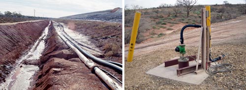
Figure 10: Seepage collection ditch (left) and a seepage well (right) (© Jon Engels)
A collection well is basically the same as a dewatering system for a mine, in that a cone of depression is created when pumping starts. Several wells can be installed around the impoundment in the same vicinity as a collection ditch. The effectiveness of the well depends on the permeability of the soil, and the depth of extraction. Such wells are expensive to install and each well has to be pumped dry and so a ditch is preferred. Collection wells can be installed at the toe of a tailings embankment to reduce the phreatic surface. The well creates a drawdown through the dam wall and can help increase the strength of the embankment. This can be used as a remedial measure for an embankment with drainage problems, and/or where there is a risk of a liquefaction event occurring.